Transition
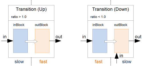
A transition block allows to connect two different time domains. It is basically a container holding two blocks. Each of the two time domains runs one of those two blocks.
Interpolator
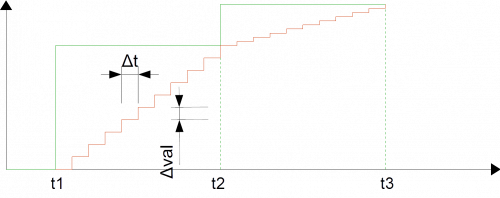
If a signal crosses from a slower time domain into a fast one, the transition block behaves as an interpolator. A change in the input signal is interpolated with small incremental steps (in amplitude as well as timestamps) on the output signal.
Such a block can be created by choosing a ratio greater then 1. The ratio must match the ratio of the periods of the two time domains. The figure above shows the resulting curve for a ratio of 10.
  Transition<Vector2> tInterpolator(10);
  TimeDomain tdSlow("td slow", 0.1, false);
  Timedomain tdFast("td fast", 0.01, true);
  tdSlow.add(tInterpolator.inBlock);
  tdFast.add(tInterpolator.outBlock);
You can configure the transition block in such a way, that it does not interpolate. In this case, each time the slower input block runs, its signal is directly put through to the output. The output signals follows the input signal without any interpolation. You can choose this behavior with setting the steady parameter to true.
Transition<Vector2> tInterpolator(10, true);
 When interpolating it is very important that the slow and the fast block of the transition block run in harmonic tasks with their periods having the same ratio as the transition block itself. For the example above, that means, that the fast part runs exactly 10 times while the slow part runs once. Time domains which run concurrently always have some timing jitter, which could lead to the ratio being sporadically 9 or 11 instead of 10. Therefore, you have to make sure to run the slow time domain only after the fast time domain has finished. This can be achieved as described in Executor. For our example this leads to
  Transition<Vector2> tInterpolator(10);
  TimeDomain tdSlow("td slow", 0.1, false);
  Periodic perSlow("perSlow", 0.1, tdSlow);
  Timedomain tdFast("td fast", 0.01, true);
  Periodic perFast("perFast", 0.1, tdFast);
  tdSlow.add(tInterpolator.inBlock);
  tdFast.add(tInterpolator.outBlock);
  perFast.after.push_back(perSlow);
  Executor.add(perFast);
Filter
A signal crossing from a fast time domain to a slower one, needs to behave like a filter. For this purpose the out block, which does the filtering, features an additional input signal. This input signal allows the filter to select a certain signal as next output signal.
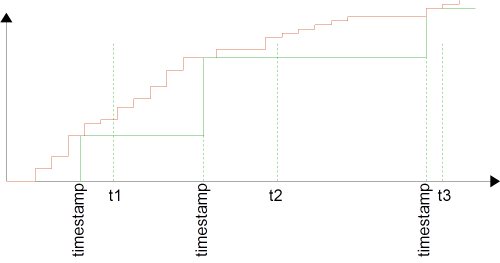
A filter block is created by choosing a ratio smaller then 1. The ratio must match the ratio of the periods of the two time domains. The figure above shows the resulting curve for a ratio of 0.1. Every time the slow time domain runs the out block of the transition block (at t1, t2, t3), the input signal of the out block is sampled. The timestamp of this signal determines which of the buffered input signals is selected and brought to the output. The selection is done in such a way that the timestamp of the selected signals is as close as possible to the timestamp of the selection signal.
  Transition<Vector2> tFilter(0.1);
  tFilter.outBlock.getIn().connect(//choose an appriopriate output signal//);
  Timedomain tdFast("td fast", 0.1, false);
  TimeDomain tdSlow("td slow", 0.01, true);
  tdFast.add(tInterpolator.inBlock);
  tdSlow.add(tInterpolator.outBlock);
You can configure the transition block in such a way, that it does not filter. In this case, each time the slower output block runs, it takes its signal directly from the actual input. The output signals follows the input signal without any filtering. You can choose this behavior with setting the steady parameter to true.
Transition<Vector2> tFilter(0.1, true);


