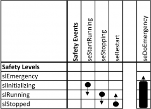
Simple System with Control and Safety System
It is time to study a basic system consisting of a control system and a safety system. The control system in this example encompasses a few blocks and one of their signals will be written to an output. As we do not have any real output we will use a simulator, see Simulator. Please build and install it. Further, you have to make sure that your example application is able to find the simulator library, see Deploying.
In the EEROS library you will find a directory with examples. For this example see SystemTest1.cpp.
Open a shell in the build directory of your EEROS library and run
$ sudo LD_LIBRARY_PATH=/home/you/work/project/install-x86/lib/ ./examples/system/systemTest1 -c examples/system/SystemTest1Config.json
 You have to run a program using real time threads with root privileges and you have to set your library path so that the simulator library can be found, see Working on the Host.
This example encompasses a safety system and a control system. The control system has one time domain running several blocks
A constant value is amplified by a gain block and added up by the integrator block. The switch is configured to automatically switch to the second input as soon as the input value reaches 20.0 ± 0.1. The signal after the switch block is finally output onto a peripheral output block.
Upon switching the block also triggers a safety event. The safety system has four safety levels.
The system will start in level slInitializing. The system will stay there for five seconds after which the time domain is started and a seStartRunning event is triggered. This will change the safety system into level slRunning. Here, the integrator sums its input signal up to where the switch reaches its trigger level. The switch will automatically switch to its second input, which is simply a constant signal and the safety event seStopping causes the safety system to change into level slStopped. It will stay there for three seconds after which it changes back into level slRunning and also switches its input back to its first input. After that the cycle restarts.
Explore Exceptions
We can demonstrate what happens …
- if you forget to connect an input to an output. To see what happens if you read from an unconnected input, comment line number 42 and recompile. This removes the connection between the constant block and the gain block. As soon as the time domain tries to run the gain block a
NotConnectedFaultis thrown. This causes the time domain to trigger aseEmergencyevent. In the safety levelslEmergencythe time domain is stopped to prevent further faults. - if you try to write a NaN value to a peripheral output. Please add line 42 and remove line 50, recompile and run the test. The integrator will add up and after some time the switch will change to the second input. The second constant block has no value assigned to it. This causes the time domain to calculate the peripheral output value to be NaN and a
NaNOutputFaultis thrown. This causes the time domain to trigger aseEmergencyevent. In the safety levelslEmergencythe time domain is stopped to prevent further faults. The value on the peripheral output block switches to a safe level. This level is defined for cases when a NaN would be output. A safe level must ensure that an real actor such as a motor won't go wild.

