This is an old revision of the document!
Control System Containing Switch Blocks
There is another example examples/controlsystem/BlockTest2. This example encompasses a safety system and a control system. It demonstrates what happens …
- if you forget to connect an input to an output
- if you try to write a NaN value to a peripheral output
The system uses an output. For this reason you will need to install a simple simulator, see simulator. The following command will run the example
$./blockTest2 -c BlockTest2Config.json
The control system consists of three blocks, a constant block, a gain block, and a peripheral output block. the safety system encompasses three safety levels as show below.
 The system will start in level
 initializing. The time domain is still in the stopped state and hence, the signal value of the output of the gain block is NaN. After three seconds the system switches to level running and the output signal is the value of the constant block times the gain of the gain block.
- In order to test what happens if you read from an unconnected input comment line number 44 and recompile. This removes the connection between the constant block and the gain block. As soon as the time domain tries to run the gain block a
NotConnectedFaultis thrown. This causes the time domain to trigger ago to emergencyevent. In the safety levelemergencythe time domain is stopped to prevent further faults. - Please add line 44 and remove line 39, recompile and run the test. The constant block has no value assigned to it. This causes the time domain to calculate the peripheral output value to be NaN and a
NaNOutputFaultis thrown. This causes the time domain to trigger ago to emergencyevent. In the safety levelemergencythe time domain is stopped to prevent further faults.
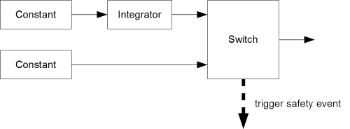
In the EEROS library you will find a directory with examples. Open a shell in the build directory of your EEROS library and run examples/controlsystem/BlockTest3.
A constant value is added up by the integrator block. The switch is configured to automatically switch to the second input as soon as the input value reaches 1.5 ± 0.1.
Upon switching the block also triggers a safety event. The safety system has two safety levels. The system stays for three seconds in the second level. After that the cycle restarts.

